
This article explains CMT (Camera Matching Transform), a transform that matches the color and tone of secondary cameras to the main camera. Preparing a CMT before production reduces differences between cameras on set and through editing, VFX, and grading, so the team can focus on creative decisions.
ACES Input Device Transforms (IDTs) are a familiar way to address differences between cameras. An IDT converts each camera into a common ACES color space. In practice, however, differences remain even after an IDT is applied.
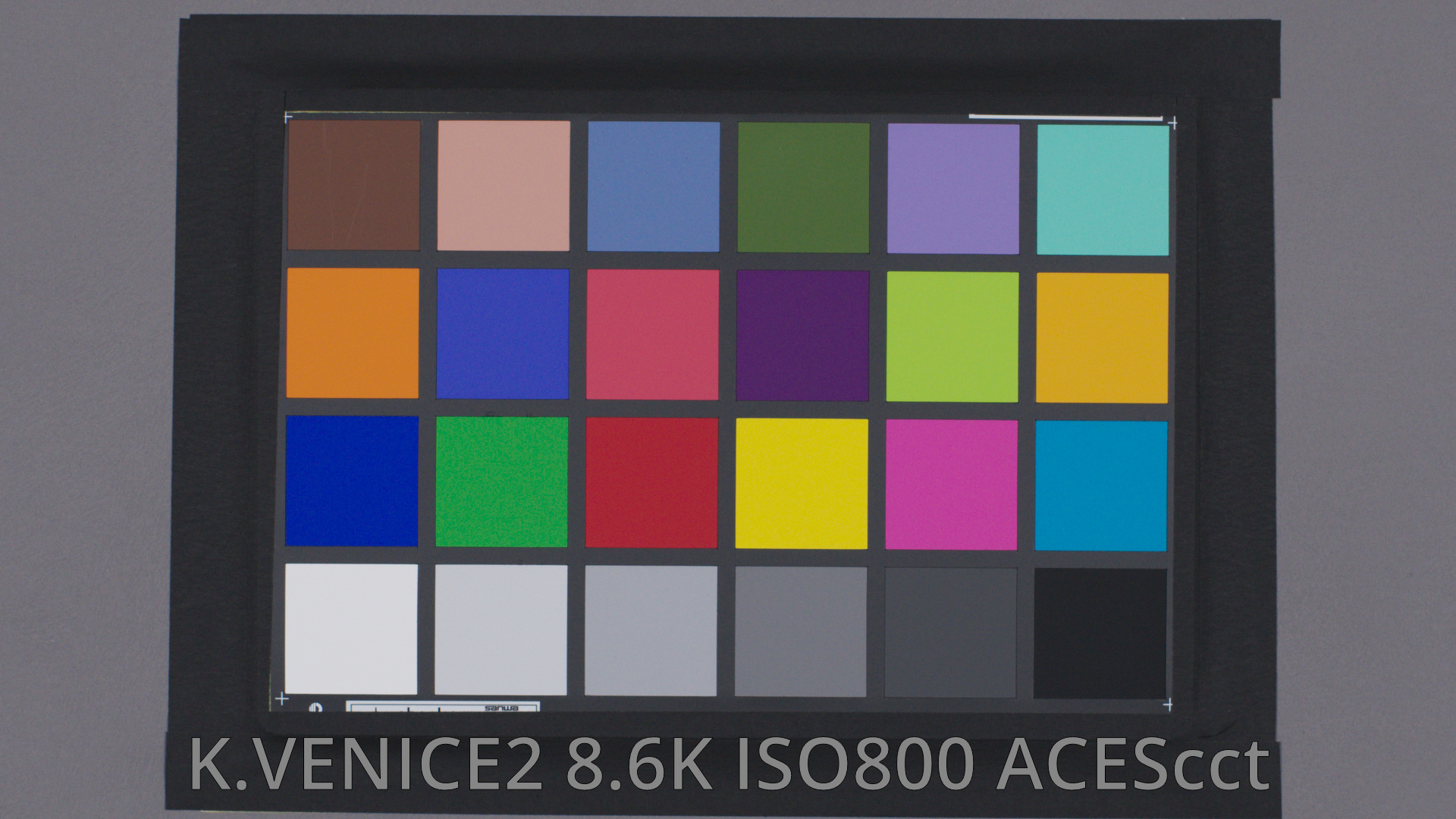
Here is an example. We filmed a Macbeth color chart with each camera under the same conditions and from the same position, then converted the images to Rec.709 through a standard ACES pipeline that includes each camera’s IDT.
We will use the VENICE 2 as the main camera.
First, we crop a small square from the center of each color patch in this chart to create the following image.
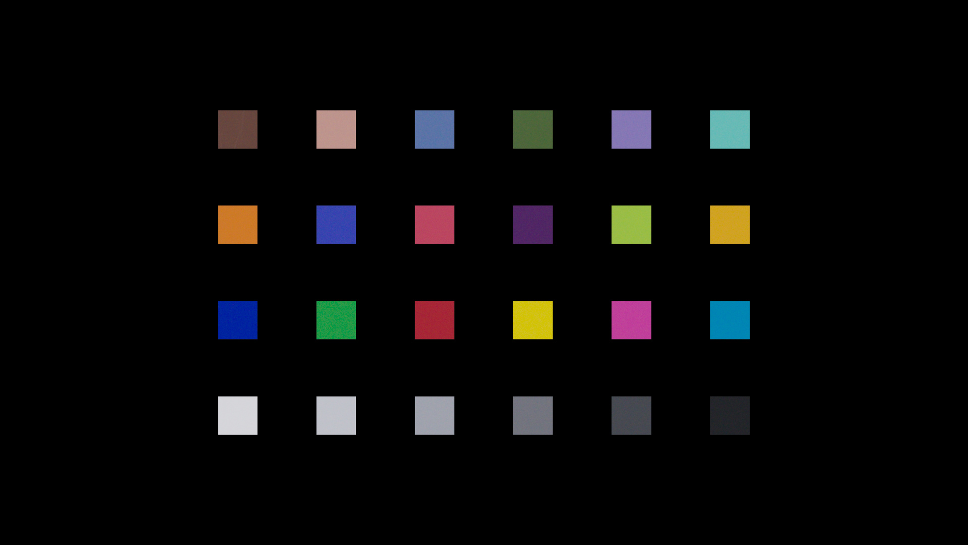
We will place those squares over the images from the other cameras and compare the differences. Here are several examples.
Alexa 35 developed in Resolve with an IDT
Let’s start with the ALEXA 35. The color pipeline is shown below. The same basic pipeline is used for the other cameras as well.

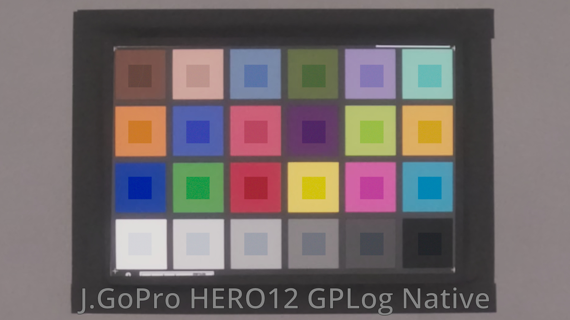
Below is the ALEXA 35 image with cropped patches from the VENICE 2 image overlaid for comparison. The same comparison images were created for the other cameras as well.
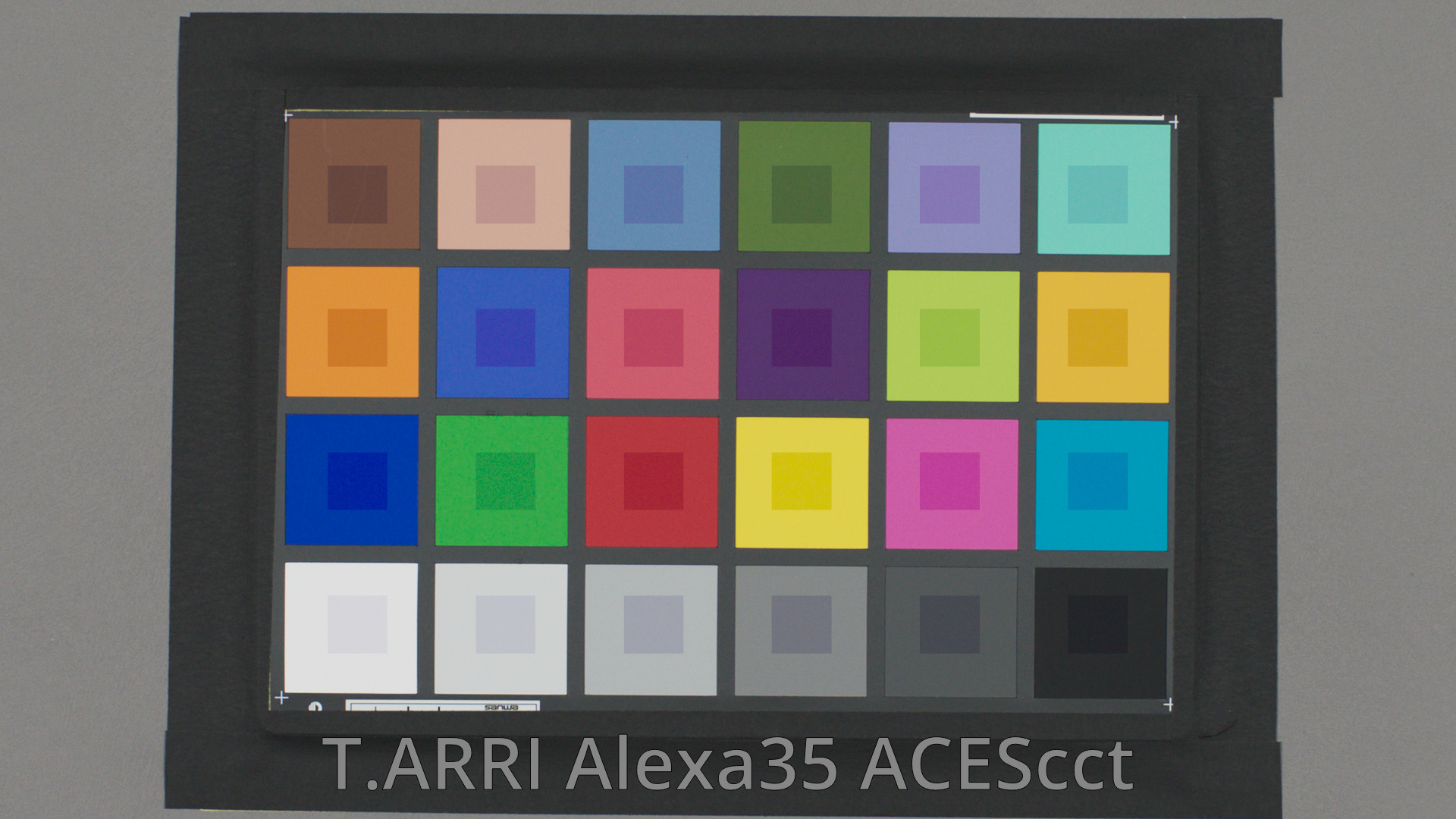
The square area visible at the center of each patch represents the VENICE 2 data, while the surrounding area represents the ALEXA 35 data.
As shown in this image, significant differences can be observed across all colors, including the gray patches.
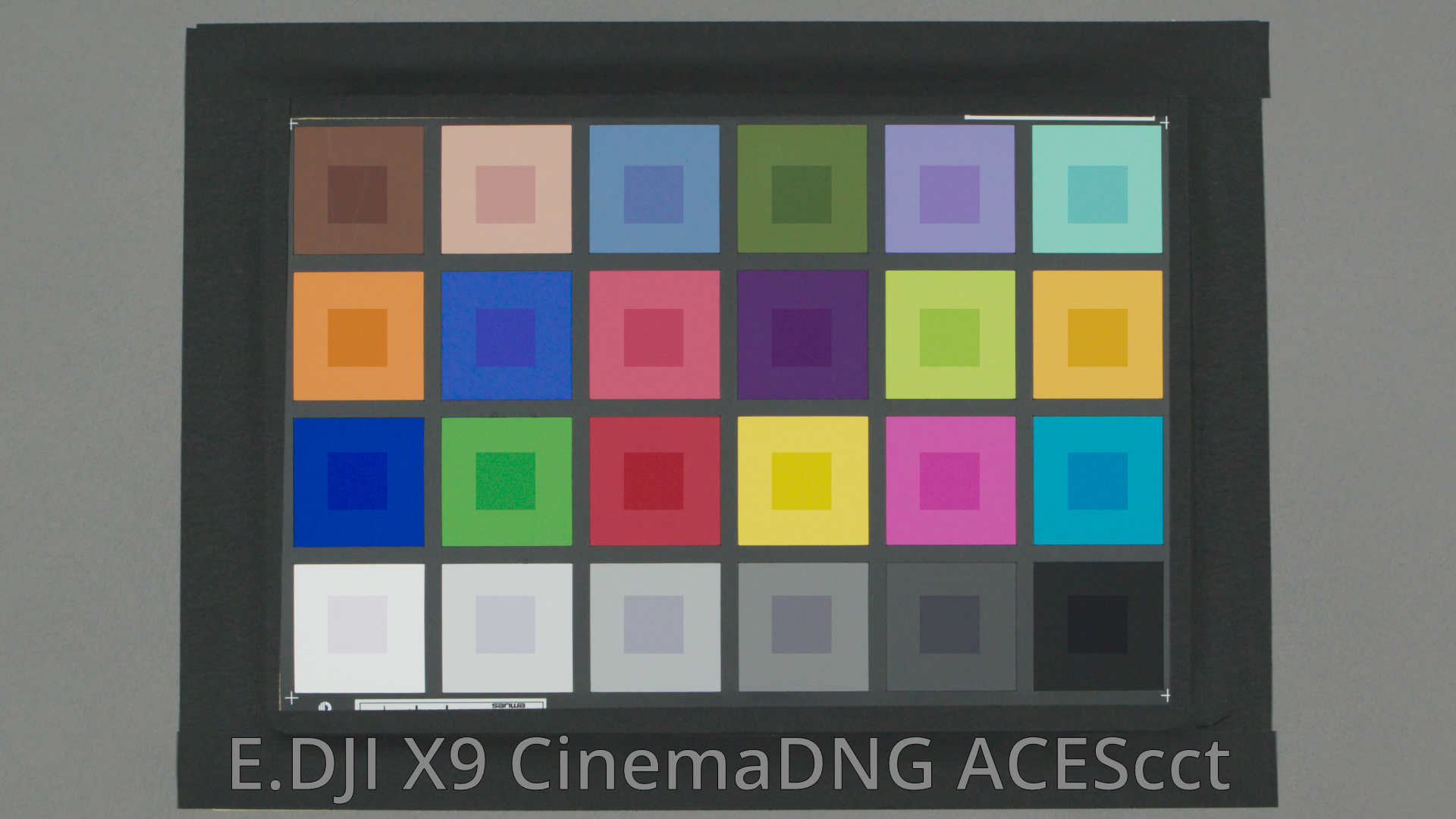
DJI X9 CinemaDNG developed in Resolve with an IDT
GoPro HERO12 GP-Log with a custom IDT created by Netflix
iPhone 15 Pro Apple Log with an IDT applied in Resolve
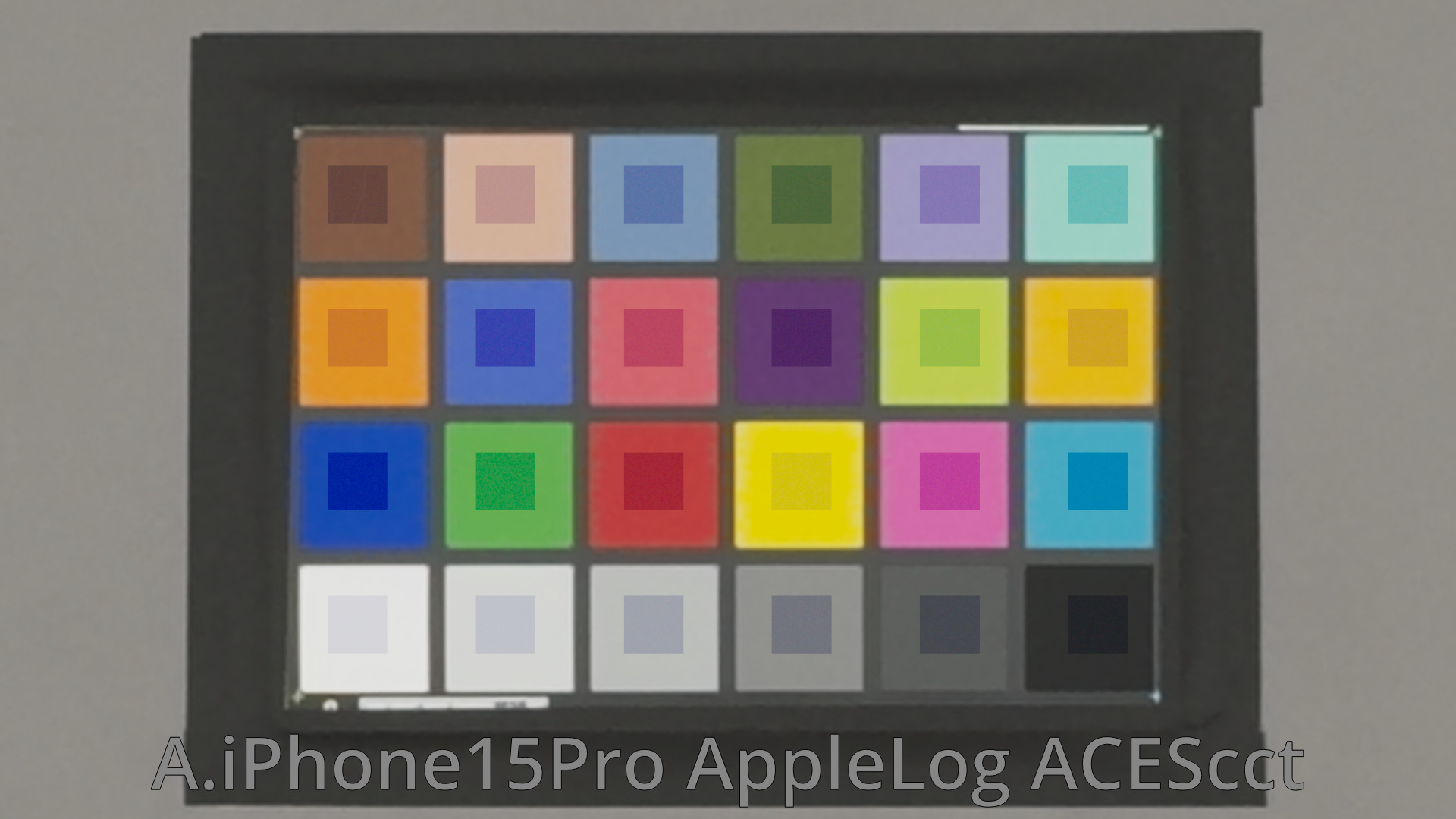
The differences are quite noticeable. All of these images were converted to Rec.709 through the same ACES color space using an IDT supplied by the manufacturer or created by a user. Several factors contribute to the differences, but exposure and white balance appear to be major ones.
Matching exposure and white balance
Next, we use the chart’s 18% gray patch to match exposure and white balance. In ACEScg, a linear color space, we calculate the factors needed to match the gray patch and apply them to the whole image. This produces a result similar to adjusting the lens aperture and white balance during capture.
“Exp/WB” shows the result after matching the gray patch this way. “IDT only” shows the IDT result from the previous section. Compare the two.
Alexa 35: gray-patch match
Let’s start with the ALEXA 35. The color pipeline is shown below.

Below is the ALEXA 35 image with cropped patches from the VENICE 2 image overlaid for comparison. The same comparison images were created for the other cameras as well.
I applied an exposure and white balance adjustment so that the third gray patch from the right in the bottom row matches perfectly.
As you can see, the differences have been significantly reduced not only in the grayscale patches, but also in the color patches. This indicates that, for this camera, most of the discrepancy can be corrected simply by adjusting exposure and white balance.
However, some small differences are still visible in the color patches.
DJI X9 CinemaDNG: gray-patch match
GoPro HERO12 GP-Log: gray-patch match
iPhone 15 Pro Apple Log: gray-patch match
Matching exposure and white balance alone brings the images much closer to the VENICE 2. Some cameras still show noticeable color differences, but their grayscale is now considerably closer.
This exposure and white-balance adjustment reflects differences between camera manufacturers, lenses, and individual units. Even by itself, it can substantially reduce the visible differences between cameras.
Adding a linear matrix
To reduce the remaining color differences, we add a linear matrix. In a linear ACES color space, we calculate a 3 × 3 RGB matrix that brings the secondary camera’s colors as close as possible to those of the main VENICE 2. The color pipeline is shown below.

“CMT (MTX)” uses this matrix to minimize the error. “Exp/WB” matches gray using exposure and white balance alone, and “IDT only” applies only the IDT. Compare the three results.
Alexa 35: matching with a CMT
DJI X9 CinemaDNG: matching with a CMT
GoPro HERO12 GP-Log: matching with a CMT
iPhone 15 Pro Apple Log: matching with a CMT
The subtle color differences that remained have also been reduced considerably.
In a real shoot, differences in framing, capture timing, and other conditions introduce additional variation. Even so, correcting the differences inherent to the cameras can make downstream work easier and reduce the need for extra adjustments.
Try the CMT creation tool
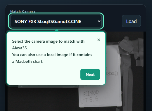
We have prepared a tool so you can experience the process of creating a CMT. It uses the Alexa 35 as the main camera and includes data from several other cameras. You can also upload your own image if it contains a Macbeth color chart.
When you open the page, a guide walks you through the steps. Follow its prompts to create and apply a CMT interactively.
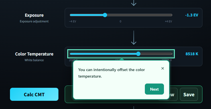
You can deliberately change the exposure or color temperature to simulate a larger mismatch.
After applying the CMT, you can use graphs to see how closely the secondary camera matches the main camera.
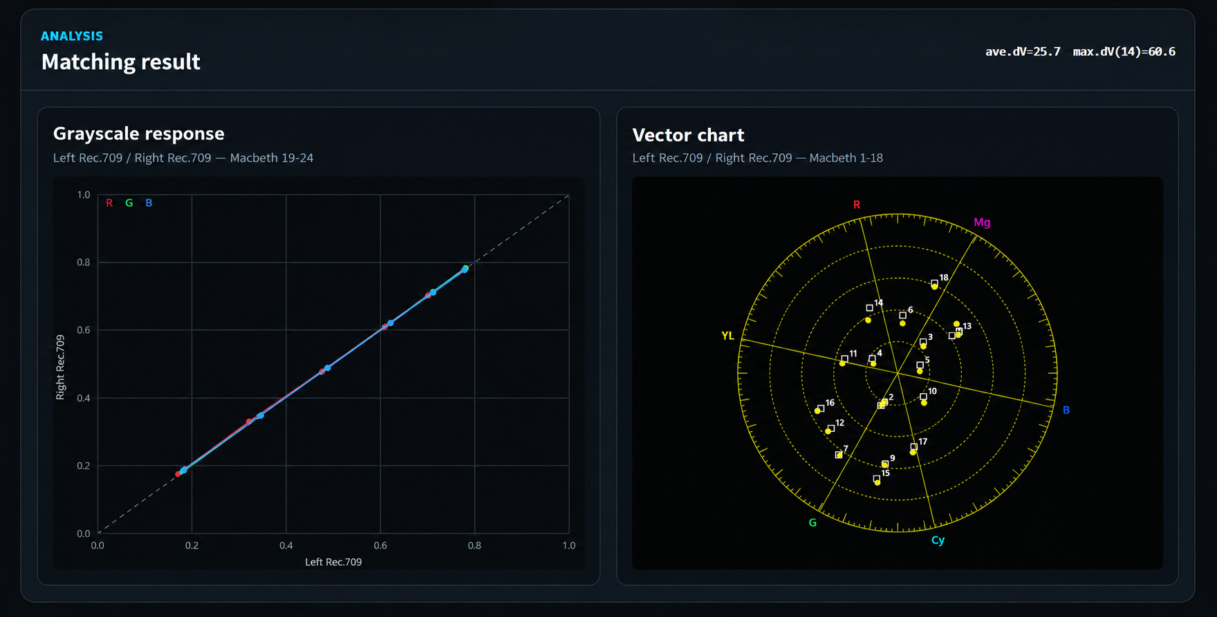
Switch the CMT on and off to compare the images and graphs. You can also download the generated CMT to your computer.

The CMT is stored in CLF, a newer LUT format. In principle, it uses ACES AP0 for both input and output. Exposure correction, white-balance correction, and the linear-matrix adjustment are recorded in separate blocks, so you can edit the file and use only selected corrections.
CAMERA MATCHING TRANSFORM · CLF
The three corrections in a CMT
<?xml version="1.0" encoding="UTF-8"?>
<ProcessList id="2aeb9b79-72f8-4e72-a070-c99d82526649" compCLFversion="3">
  <Description>Source image: iPhone15ProBM AppleLogRec2020.dpx; IDT: AppleLog to AP0.clf; PixCal CMT mode=3 pureBlackCV=153.937444657</Description>
  <InputDescriptor>ACES2065-1</InputDescriptor>
<OutputDescriptor>ACES2065-1</OutputDescriptor><Matrix id="030.Calculated LinearMTX to AP0" inBitDepth="32f" outBitDepth="32f">
<Array dim="3 3">
1.14911856164 -0.0527749477846 -0.104443380555
0.0302447391232 1.05919955118 -0.0912936221523
0.0589312427103 8.33630994501e-06 0.944403952714
</Array>
</Matrix><ASC_CDL id="050.matching exposure with MainCam" inBitDepth="32f" outBitDepth="32f" style="FwdNoClamp">
<SOPNode><Slope>2.53799189272 2.53799189272 2.53799189272</Slope><Offset>0 0 0</Offset><Power>1 1 1</Power></SOPNode>
<SatNode><Saturation>1</Saturation></SatNode>
</ASC_CDL><ASC_CDL id="060.matching white balance with MainCam" inBitDepth="32f" outBitDepth="32f" style="FwdNoClamp">
<SOPNode><Slope>1.02260577919 1 0.899897488624</Slope><Offset>0 0 0</Offset><Power>1 1 1</Power></SOPNode>
<SatNode><Saturation>1</Saturation></SatNode>
</ASC_CDL></ProcessList>If you would like to introduce CMT into a production workflow, please contact us.